


LCD
Update time:2018-04-13 Views:5431
Introduction
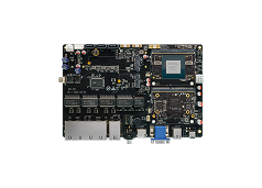
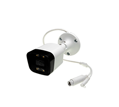
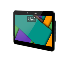
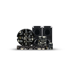
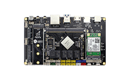
Firefly-RK3399 has two LCD screen interface, one is EDP, one is LVDS, the corresponding interface board position is as follows: 
Configuration
The AIO-3399J default configuration file kernel/arch/arm64/configs/firefly_defconfighave set up the LCD configuration file, if you want to modify, please note that the following configuration: :
CONFIG_LCD_MIPI=y
CONFIG_MIPI_DSI=y
CONFIG_RK32_MIPI_DSI=y
Configure DTS
LCD pins configuration
LVDS LCD
The AIO-3399J SDK has an LCD DTS file in kernel/arch/arm64/boot/dts/rockchip/rk3399-firefly-aio-lvds.dts, From this file, we can see the following statement: :
/ {
    model = "AIO Board lvds (Android)";
    compatible = "rockchip,android", "rockchip,rk3399-firefly-lvds", "rockchip,rk3399";

    test-power {
        status = "okay";
    };

```

&dsi {
    status = "okay";
    dsi_panel: panel {
        compatible ="simple-panel-dsi";
        reg = <0>;
        //ddc-i2c-bu
        //power-supply = <&vcc_lcd>;
        //pinctrl-0 = <&lcd_panel_reset &lcd_panel_enable>;
        backlight = <&backlight>;
        /*
        enable-gpios = <&gpio1 1 GPIO_ACTIVE_LOW>;
        reset-gpios = <&gpio4 29 GPIO_ACTIVE_LOW>;
        */
        dsi,flags = <(MIPI_DSI_MODE_VIDEO | MIPI_DSI_MODE_VIDEO_BURST | MIPI_DSI_MODE_LPM | MIPI_DSI_MODE_EOT_PACKET)>;
        dsi,format = <MIPI_DSI_FMT_RGB888>;
        //bus-format = <MEDIA_BUS_FMT_RGB666_1X18>;
        dsi,lanes = <4>;

        dsi,channel = <0>;

        enable-delay-ms = <35>;
        prepare-delay-ms = <6>;

        unprepare-delay-ms = <0>;
        disable-delay-ms = <20>;

        size,width = <120>;
        size,height = <170>;

        status = "okay";
...
        power_ctr: power_ctr {
               rockchip,debug = <0>;
               lcd_pwr_en: lcd-pwr-en {
                       gpios = <&gpio3 16 GPIO_ACTIVE_HIGH>;
                       pinctrl-names = "default";
                       pinctrl-0 = <&lcd_panel_pwr_en>;
                       rockchip,delay = <10>;
               };

               lcd_rst: lcd-rst {
                       gpios = <&gpio2 27 GPIO_ACTIVE_HIGH>;
                       pinctrl-names = "default";
                       pinctrl-0 = <&lcd_panel_reset>;
                       rockchip,delay = <6>;
               };
           };
...
&pinctrl {
    lcd-panel {
        lcd_panel_reset: lcd-panel-reset {
            rockchip,pins = <2 27 RK_FUNC_GPIO &pcfg_pull_down>;
        };

        lcd_panel_pwr_en: lcd-panel-pwr-en {
            rockchip,pins = <3 16 RK_FUNC_GPIO &pcfg_pull_down>;
        };

    };
The power control pins of the LCD are defined here: :
lcd_pwr_en:(GPIO3_C0)GPIO_ACTIVE_HIGH
lcd_rst:(GPIO2_D3)GPIO_ACTIVE_HIGH
They are active-high. For details on pin configuration, refer to the "GPIO" section.
Backlight Configuration
In DTS file kernel/arch/arm64/boot/dts/rockchip/rk3399-firefly-core.dtsi configuration of the backlight information.
/ {
    compatible = "rockchip,rk3399-firefly-core", "rockchip,rk3399";
    backlight: backlight {
        status = "disabled";
        compatible = "pwm-backlight";
        pwms = <&pwm0 0 25000 0>;
        brightness-levels = <
              0   1   2   3   4   5   6   7
              8   9  10  11  12  13  14  15
             16  17  18  19  20  21  22  23
             24  25  26  27  28  29  30  31
             32  33  34  35  36  37  38  39
             40  41  42  43  44  45  46  47
             48  49  50  51  52  53  54  55
             56  57  58  59  60  61  62  63
             64  65  66  67  68  69  70  71
             72  73  74  75  76  77  78  79
             80  81  82  83  84  85  86  87
             88  89  90  91  92  93  94  95
             96  97  98  99 100 101 102 103
            104 105 106 107 108 109 110 111
            112 113 114 115 116 117 118 119
            120 121 122 123 124 125 126 127
            128 129 130 131 132 133 134 135
            136 137 138 139 140 141 142 143
            144 145 146 147 148 149 150 151
            152 153 154 155 156 157 158 159
            160 161 162 163 164 165 166 167
            168 169 170 171 172 173 174 175
            176 177 178 179 180 181 182 183
            184 185 186 187 188 189 190 191
            192 193 194 195 196 197 198 199
            200 201 202 203 204 205 206 207
            208 209 210 211 212 213 214 215
            216 217 218 219 220 221 222 223
            224 225 226 227 228 229 230 231
            232 233 234 235 236 237 238 239
            240 241 242 243 244 245 246 247
            248 249 250 251 252 253 254 255>;
        default-brightness-level = <200>;
    };
......
};
Pwms: the attribute of PWM. The Firelfy-RK3399 use pwm0. 25000ns is the cycle of PWM(40 KHz). brightness-level: array for back light, the max value is 255. The configuration of dark and light area default-brightness-level: default brightness, the range of this value is 0~255.
enable-gpios: the enable pin of back light. See the documentations in the follow path for more information: Documentation/devicetree/bindings/video/backlight/pwm-backlight.txt
In the DTS file: the backlight information is configured in kernel/arch/arm64/boot/dts/rockchip/rk3399-firefly-core.dtsi, as follows:
&backlight {
    status = "okay";
    enable-gpios = <&gpio1 1 GPIO_ACTIVE_HIGH>;
    brightness-levels = < 150 151
    152 153 154 155 156 157 158 159
    160 161 162 163 164 165 166 167
    168 169 170 171 172 173 174 175
    176 177 178 179 180 181 182 183
    184 185 186 187 188 189 190 191
    192 193 194 195 196 197 198 199
    200 201 202 203 204 205 206 207
    208 209 210 211 212 213 214 215
    216 217 218 219 220 221 222 223
    224 225 226 227 228 229 230 231
    232 233 234 235 236 237 238 239
    240 241 242 243 244 245 246 247
    248 249 250 251 252 253 254 255>;
};
The configuration of display sequence
LVDS LCD
The Timing of the LVDS screen is written in the DTS file, and the following statements can be seen in the kernel/arch/arm64/boot/dts/rockchip/rk3399-firefly-aio-lvds.dts.
disp_timings: display-timings {
    native-mode = <&timing0>;
    timing0: timing0 {
         clock-frequency = <80000000>;
         hactive = <768>;
         vactive = <1024>;
         hsync-len = <20>;   //20, 50
         hback-porch = <130>; //50, 56
         hfront-porch = <150>;//50, 30
         vsync-len = <40>;
         vback-porch = <130>;
         vfront-porch = <136>;
         hsync-active = <0>;
         vsync-active = <0>;
         de-active = <0>;
         pixelclk-active = <0>;
           };
    }
}
As to timing’s attribute, you can take a look at this picture.

Init Code
LVDS LCD
The LVDS lcd needs to send the initialization instructions to make it work.
Dts
可以在kernel/arch/arm64/boot/dts/rockchip/rk3399-firefly-aio-lvds.dts中可以看到lvds的初始化指令列表:
&dsi {
            status = "okay";

        ```
        panel-init-sequence = [
    29 00 06 3C 01 09 00 07 00
    29 00 06 14 01 06 00 00 00
    29 00 06 64 01 0B 00 00 00
    29 00 06 68 01 0B 00 00 00
    29 00 06 6C 01 0B 00 00 00
    29 00 06 70 01 0B 00 00 00
    29 00 06 34 01 1F 00 00 00
    29 00 06 10 02 1F 00 00 00
    29 00 06 04 01 01 00 00 00
    29 00 06 04 02 01 00 00 00
    29 00 06 50 04 20 01 F0 03
    29 00 06 54 04 32 00 B4 00
    29 00 06 58 04 80 07 48 00
    29 00 06 5C 04 0A 00 19 00
    29 00 06 60 04 38 04 0A 00
    29 00 06 64 04 01 00 00 00
    29 01 06 A0 04 06 80 44 00
    29 00 06 A0 04 06 80 04 00
    29 00 06 04 05 04 00 00 00
    29 00 06 80 04 00 01 02 03
    29 00 06 84 04 04 07 05 08
    29 00 06 88 04 09 0A 0E 0F
    29 00 06 8C 04 0B 0C 0D 10
    29 00 06 90 04 16 17 11 12
    29 00 06 94 04 13 14 15 1B
    29 00 06 98 04 18 19 1A 06
    29 02 06 9C 04 33 04 00 00
        ];

        panel-exit-sequence = [
            05 05 01 28
            05 78 01 10
        ];
        ```
        };
The format and description of the command may be referred to as the following annexes:
![]() Rockchip DRM Panel Porting Guide.pdf
Rockchip DRM Panel Porting Guide.pdf
kernel
The sending instruction can see the operation in kernel/drivers/gpu/drm/panel/panel-simple.c:
    static int panel_simple_enable(struct drm_panel *panel)
{
    struct panel_simple *p = to_panel_simple(panel);
    int err;
    if (p->enabled)
        return 0;
    DBG("enter\n");
    if (p->on_cmds) {
        err = panel_simple_dsi_send_cmds(p, p->on_cmds);
        if (err)
            dev_err(p->dev, "failed to send on cmds\n");
    }
    if (p->desc && p->desc->delay.enable) {
        DBG("p->desc->delay.enable=%d\n", p->desc->delay.enable);
        msleep(p->desc->delay.enable);
    }
    if (p->backlight) {
        DBG("open backlight\n");
        p->backlight->props.power = FB_BLANK_UNBLANK;
        backlight_update_status(p->backlight);
    }
    p->enabled = true;
    return 0;
}
U-boot
The sending instruction can see the operation in u-boot/drivers/video/rockchip-dw-mipi-dsi.c:
static int rockchip_dw_mipi_dsi_enable(struct display_state *state)
{
    struct connector_state *conn_state = &state->conn_state;
    struct crtc_state *crtc_state = &state->crtc_state;
    const struct rockchip_connector *connector = conn_state->connector;
    const struct dw_mipi_dsi_plat_data *pdata = connector->data;
    struct dw_mipi_dsi *dsi = conn_state->private;
    u32 val;
    DBG("enter\n");
    dw_mipi_dsi_set_mode(dsi, DW_MIPI_DSI_VID_MODE);
    dsi_write(dsi, DSI_MODE_CFG, ENABLE_CMD_MODE);
    dw_mipi_dsi_set_mode(dsi, DW_MIPI_DSI_VID_MODE);
    if (!pdata->has_vop_sel)
        return 0;
    if (pdata->grf_switch_reg) {
        if (crtc_state->crtc_id)
            val = pdata->dsi0_en_bit | (pdata->dsi0_en_bit << 16);
        else
            val = pdata->dsi0_en_bit << 16;
        writel(val, RKIO_GRF_PHYS + pdata->grf_switch_reg);
    }
    debug("vop %s output to dsi0\n", (crtc_state->crtc_id) ? "LIT" : "BIG");
    //rockchip_dw_mipi_dsi_read_allregs(dsi);
    return 0;
}


