Kernel
Update time:2018-04-13 Views:2114
Introduction
This chapter describe QN902x system structure and BLE kernel basic introduction,Mainly to the introduction of some basic concepts and understanding.
QN902x System Struct
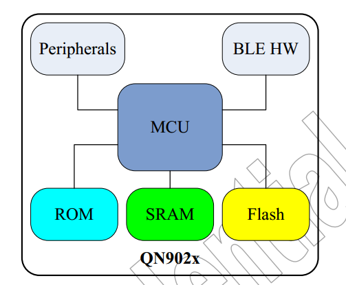
QN902x has three memory,respectively:
96K ROM : The Firmware in the ROM contains the Kernel
and BLE protocol stack which are only provided as APIs.
64K SRAM : The code executed in the SRAM is called
Application project. It contains eight separate block.
128K FLASH : The FLASH can be used to store the
application program and the user data which should be saved when system is power-down.
The software platform of QN902x consists of two main parts :
The code executed in the ROM is called Firmware.
The code executed in the SRAM is called Application project. 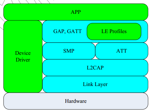
Quintic QN902x provides the most flexible platform for wireless applications, which supports three working modes:
SOC(System On Chip)Mode
NP(Network Processor)Mode
HCI(Host Control interface)Mode
SOC Mode
In the Wireless SoC Mode the link layer, host protocol, profiles and application all run on the QN902x as a single chip solution. This is the work mode that the application samples are used.
Network Processor Mode
In the Network Processor Mode the link layer, host protocols and profiles run on the QN902x, and the application runs on the external microcontroller or PC. These two components communicate via ACI (Application Control Interface), which are provided on QN902x.
HCI Mode
In the Controller Mode only the link layer runs on the QN902x. The host protocol, profiles and application all run on the external microcontroller or PC. These two components communicate via HCI. Generally this mode is not used in the product design except for the product testing.
System Kernel Overview
Quintic’s BLE protocol is composed of LL, L2CAP, SMP, ATT, GATT, GAP, Profiles and APP Layer. Each protocol layer may be divided into a number of sub-layers. These layers have these own state machine which is managed by an individual task. The kernel defines task descriptor to help each task to manage their state machine and message processing handler.
When the QN902x is powered on or reset, the bootloader is activated firstly. It looks for a connection command from UART and SPI interface for a while to determine which mode to go:
If the connection command is found, the bootloader enters into Program Mode. It starts the ISP command parser which is implemented to process host commands, and then the host could send the ISP commands to download application, to verify correction of downloaded application, to branch to the application entry point and to finish other features provided by bootloader.
If no connection command found from UART and SPI interface, the bootloader enters into Load Mode. The bootloader copies application stored in the flash to internal SRAM, and then jump to the address of application entry point in the SRAM.
When the bootloader has already prepared application runtime environment (copy the Application to correct SRAM location), it sets PC to the entry point of Reset Handler of the Application. At the beginning of main function has Initialize BLE Hardware,System Clock,BLE Stack and sleep,then jump to ke_schedule function.ke_schedule function is a function in System kernel and mask in the ROM.we can use it with QN9020 API Programming Guide.This routine checks the message queue, and implement message deliver.
Events
When the scheduler is called in the main loop of the background, the kernel checks if the event field is non-null, gets the one with highest priority and executes the event handlers for which the corresponding event bit is set.
There are total 32 events, and the highest priority events are used by BLE stack. So users have 24 events could be used in the application. The following snippet is a pseudo code of event scheduler.
Define Events
User can define 0 ~ 23, a total of 24 events, the higher the number, the greater the level.
#define EVENT_BUTTON1_PRESS_ID 0
Define Event Callback Function
User can define Event Callback function,sent a Assert when define faild.
   if(KE_EVENT_OK != ke_evt_callback_set(EVENT_BUTTON1_PRESS_ID,
                                           app_event_button1_press_handler))
   {
       ASSERT_ERR(0);
   }  //usr_design.c----->usr_init
Set a Event
After sets a Evens, the system will call the event callback function, until the event is clear.
ke_evt_set(1UL << EVENT_BUTTON1_PRESS_ID); //usr_design.c------>usr_button1_cb
Clear Event
Event processing is completed, clear the event or events list is not empty, the system couldn't get into a deep sleep mode , will greatly increase the power consumption.
ke_evt_clear(1UL << EVENT_BUTTON1_PRESS_ID);
Message
A message is the entity that is exchanged between two tasks.
MSG Struct:
hdr List header for chaining.
hci_type Type of HCI data (used by the HCI only, user do not need to fill it).
hci_offset Offset of the HCI data in the message (used by the HCI only, user do not need to fill
it).
hci_len Length of the HCI traffic (used by the HCI only, user do not need to fill it).
id Message identifier.
dest_id Destination task identifier.
src_id Source task identifier.
param_len Parameter embedded structure length.
param Parameter embedded structure.
Transmission of messages is done in 3 steps. First the message structure must be allocated in the kernel heap by the sender task calling the function ‘ke_msg_alloc()’ or the macro ‘KE_MSG_ALLOC’ which is a convenient wrapper for ke_msg_alloc(). In order to store the message data conveniently, the pointer of the element ‘param’ in the message structure will be returned. Second, the user will fill the message parameter which pointer is returned by ke_msg_alloc(). Third, call ke_msg_send() to pushed message into the kernel ‘s message queue. The function ke_msg_send() will signal the kernel that there is at least one message in message queue by setting message exist flag
Create Message
ke_msg_alloc function allocates memory for a message that has to be sent. The memory is allocated dynamically on the heap and the length of the variable parameter structure has to be provided in order to allocate the correct size.Create a msg with a id of APP_SYS_UART_DATA_IND:
struct app_uart_data_req *req =
ke_msg_alloc(APP_SYS_UART_DATA_IND,
                                                     TASK_APP,
                                                     TASK_NONE,
                                                     sizeof(struct app_uart_data_req) + (app_uart_env.len - 1));
Fill in the variable parameter
req->len = app_uart_env.len;
memcpy(req->data, app_uart_env.buf_rx, app_uart_env.len);
Send Message
 So easy!
 ke_msg_send(req);
Message scheduler will free the msg until it receive a reply of KE_MSG_CONSUMED.
Task
One task is defined by its task type and task descriptor Task defined
Task Descriptor
state_handler The messages that it is able to receive in each of its states
default_handler The messages that it is able to receive in the default state
state The current state of each instance of the task
state_max The number of states of the task
idx_max The number of instances of the task
state_handler
In proxr example:
 /// Disabled State handler definition.
 const struct ke_msg_handler proxr_disabled[] =
 {
     {PROXR_CREATE_DB_REQ,   (ke_msg_func_t) proxr_create_db_req_handler },
 };

 /// Idle State handler definition.
 const struct ke_msg_handler proxr_idle[] =
 {
     {PROXR_ENABLE_REQ,      (ke_msg_func_t) proxr_enable_req_handler },
 };

 /// Connected State handler definition.
 const struct ke_msg_handler proxr_connected[] =
 {
     {GATT_WRITE_CMD_IND,    (ke_msg_func_t) gatt_write_cmd_ind_handler},
 };

 /// Specifies the message handler structure for every input state.
 const struct ke_state_handler proxr_state_handler[PROXR_STATE_MAX] =
 {
     [PROXR_DISABLED]    = KE_STATE_HANDLER(proxr_disabled),
     [PROXR_IDLE]        = KE_STATE_HANDLER(proxr_idle),
     [PROXR_CONNECTED]   = KE_STATE_HANDLER(proxr_connected),
 };
default_handler
In proxr,default_handler described a msg of GAP_DISCON_CMP_EVT,so proxr can disconnect a connect with send a msg of GAP_DISCON_CMP_EVT in any time.
 /// Default State handlers definition
 const struct ke_msg_handler proxr_default_state[] =
 {
     {GAP_DISCON_CMP_EVT,    (ke_msg_func_t) gap_discon_cmp_evt_handler},
 };
/// Specifies the message handlers that are common to all states. const struct ke_state_handler proxr_default_handler = KE_STATE_HANDLER(proxr_default_state);
state
 /// Defines the place holder for the states of all the task instances.
 ke_state_t proxr_state[PROXR_IDX_MAX];
state_max
State list:
 /// Possible states of the PROXR task
 enum
 {
     /// Disabled State
     PROXR_DISABLED,
     /// Idle state
     PROXR_IDLE,
     /// Connected state
     PROXR_CONNECTED,

     /// Number of defined states.
     PROXR_STATE_MAX
 };
idx_max
 /// Maximum number of Proximity Reporter task instances
 #define PROXR_IDX_MAX                 (1)
PROXR task descriptor
 // Register PROXR task into kernel
 void task_proxr_desc_register(void)
 {
     struct ke_task_desc task_proxr_desc;

     task_proxr_desc.state_handler = proxr_state_handler;
     task_proxr_desc.default_handler=&proxr_default_handler;
     task_proxr_desc.state = proxr_state;
     task_proxr_desc.state_max = PROXR_STATE_MAX;
     task_proxr_desc.idx_max = PROXR_IDX_MAX;

     task_desc_register(TASK_PROXR, task_proxr_desc);
 }
Task API
Get Current State
Get Current Task State to (fireblue/Demo_BLE/prj_proxr/src/usr_design.c)
 case APP_SYS_BUTTON_1_TIMER:
           // make sure the button is pressed
           if(gpio_read_pin(BUTTON1_PIN) == GPIO_LOW)
           {
               if(APP_IDLE == ke_state_get(TASK_APP))
               {
                   struct app_proxr_env_tag *app_proxr_env = &app_env.proxr_ev;
                   if(!app_proxr_env->enabled)
                   {
                       // start adv
                       app_gap_adv_start_req(GAP_GEN_DISCOVERABLE|GAP_UND_CONNECTABLE,
                               app_env.adv_data, app_set_adv_data(GAP_GEN_DISCOVERABLE),
                               app_env.scanrsp_data, app_set_scan_rsp_data(app_get_local_service_flag()),
                               GAP_ADV_FAST_INTV1, GAP_ADV_FAST_INTV2);

 #if (QN_DEEP_SLEEP_EN)
                       // prevent entering into deep sleep mode
                       sleep_set_pm(PM_SLEEP);
 #endif
                   }
               }
               else if(APP_ADV == ke_state_get(TASK_APP))
               {
                   // stop adv
                   app_gap_adv_stop_req();

 #if (QN_DEEP_SLEEP_EN)
                   // allow entering into deep sleep mode
                   sleep_set_pm(PM_DEEP_SLEEP);
 #endif
               }
           }
           break;
Set Current State
fireblue/Demo_BLE/src/profile/proxr_task.c
 // Go to Connected state
 ke_state_set(TASK_PROXR, PROXR_CONNECTED);
Message Scheduler
The message scheduler provides a mechanism to transmit one or more messages to a task.When the scheduler is executed, it checks if the message queue is not empty, finds the corresponding message handler, and executes the handler. The scheduler will take care of freeing processed message. If the message cannot be consumed by the destination task at this time, the message handler will return status ‘KE_MSG_SAVED’. Then the scheduler holds this message in the saved message queue until the task state changes. When one task state is changed, the kernel looks for all of the messages destined to this task that have been saved and inserts them into message queue again. These messages will be scheduled at the next scheduling round.
Timer Scheduling
The kernel provides timer services including start and stop timer. The timer runs by absolute time counter. Timers are implemented by the mean of a reserved queue of delayed messages, and timer messages do not have parameters. Time is defined as duration. The minimal step is 10ms. The minimal duration is 20ms and the maximal duration is 300s.
Set A Timer Event
example:Send a msg of APP_PROXR_ALERT_STOP_TIMER after 500ms.
 buzzer_on(BUZZ_VOL_LOW);
 ke_timer_set(APP_PROXR_ALERT_STOP_TIMER, TASK_APP, 500);    // 5 seconds
Clear Timer Event when over or will won't be able to enter a state of deep sleep, greatly increase the power consumption.
 buzzer_off();
 ke_timer_clear(APP_PROXR_ALERT_STOP_TIMER, TASK_APP);
Include
use with include this Header file
| Header file | declare |
|---|---|
| ke_msg.h | Contains the definition related to message scheduling and the primitives called to allocate, send or free a message. |
| ke_task.h | Contains the definition related to kernel task management |
| ke_timer.h | Contains the primitives called to create or delete a timer. |
| ble.h | Contains the definition related to scheduler. |
| lib.h | lib.h |


