


The First Sketch of Fireduino
Update time:2018-04-13 Views:6332
Operating environment
The following operating environment for this tutorial:
Operating system:Windows 7 Ultimate 64bits
Arudino IDE: 1.6.6
Fireduino SDK 0.9.4
Fireduino development board driver have been successfully installed.
Example
This chapter introduces the Arduino IDE comes with Blink example how to use the Fireduino.
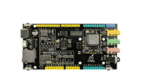
Fireduino differences with the Arduino LED interface
Fireduino and Arduino is different in the design of the LED interface,Fireduino provides two LED for the user,respectively in the digital pin 3 and pin 9,while the Arduino only provides a LED,and is connected to the digital pin 13.Due to the LED is mainly used for indicating state,so this difference will not affect the function of the development board to use almost,but it cannot be used directly compiled in routine,need to do some simple modification.These simple changes are detailed below.
Blink process introduction
Blink sample mainly shows how to set a digital pin model to the OUTPUT,and let the pin OUTPUT high level,OUTPUT low level again after a second delay,then one second delay again. So an infinite loop. When setting on the LED digital pins,when the digital pins output high level,LED lights down,when the digital pins output low level,the LED lights up. So Blink program eventually phenomenon is LED every second change an on/off state,form a flashing light.
操作步骤
按照以下步骤创建 Fireduino 第一个项目:
第一步: 依次点击 Arduino IDE 菜单栏 : 文件>>示例>>01.Basic>>Blink.
第二步: 依次点击 Arduino IDE 菜单栏 : 工具>>开发板管理器>>Fireduino。
第三步: 依次点击 Arduino IDE 菜单栏 : 工具>>端口>>Fireduino对应串口端口(板载USB转串口的端口号)
第四步: 先点击编译按钮,确认代码是否可以编译通过。如果编译通过,说明我们 Fireduino SDK 已经安装成功。

代码应如下:
/*
  Blink
  Turns on an LED on for one second, then off for one second, repeatedly.

  Most Arduinos have an on-board LED you can control.On the Uno and
  Leonardo,it is attached to digital pin 13.If you're unsure what
  pin the on-board LED is connected to on your Arduino model,check
  the documentation at http://www.arduino.cc

  This example code is in the public domain.

  modified 8 May 2014
  by Scott Fitzgerald
 */
 // the setup function runs once when you press reset or power the boardvoid setup() {
  // initialize digital pin 13 as an output.
  pinMode(3, OUTPUT);} // the loop function runs over and over again forevervoid loop() {
  digitalWrite(3, HIGH);   // turn the LED on (HIGH is the voltage level)
  delay(1000);              // wait for a second
  digitalWrite(3, LOW);    // turn the LED off by making the voltage LOW
  delay(1000);              // wait for a second}
At this point,we have completed the first project of Fireduino created and compiled,but we just adapted the original system example,fit into the Fireduino development board,and compile the program,we didn't see the program should have the phenomenon which we designed in development board.This is because we use the Arduino IDE are compiled firmware on a PC,need to be uploaded to the Fireduino development board after we can see just the effect of design, otherwise the firmware can only be stored in a PC,instead of Fireduino.The next chapter we introduce how to upload the firmware file to Fireduino.


