


UART
Update time:2018-04-13 Views:3356
Introduction
AIO-3399J supports SPI bridging / extending the functions of 4 enhanced functional serial ports (UART), respectively, UART1, UART2, RS232, RS485. Each UART has a 256 byte FIFO buffer for data reception and transmission. Among them:
UART1 ~ UART3 are TTL level interface, RS232 is RS232 level interface, RS485 is RS485 level interface
Each sub-channel UART baud rate, word length, parity format can be set independently, up to 2Mbps communication rate
Each sub-channel has a receive / send independent 256 BYTE FIFO, FIFO interrupt can be programmed according to user needs Trigger point
With sub-serial port receive FIFO timeout interrupt
Support for start bit error detection
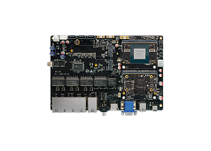
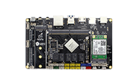
AIO-3399J development board serial interface interface as follows:

DTS Config
The spi to uart node have already been created in kernel/arch/arm64/boot/dts/rockchip/rk3399-firefly-port.dtsi:
 &spi1 {
     spi_wk2xxx: spi_wk2xxx@00{
         status = "disabled";
         compatible = "firefly,spi-wk2xxx";
         reg = <0x00>;
         spi-max-frequency = <10000000>;
         power-gpio = <&gpio2 4 GPIO_ACTIVE_HIGH>;
      reset-gpio = <&gpio1 17 3 GPIO_ACTIVE_HIGH>;
         irq-gpio = <&gpio1 2 IRQ_TYPE_EDGE_FALLING>;
         cs-gpio = <&gpio1 10 GPIO_ACTIVE_HIGH>;
         /* rk3399 driver support SPI_CPOL | SPI_CPHA | SPI_CS_HIGH */
         //spi-cpha;     /* SPI mode: CPHA=1 */
         //spi-cpol;     /* SPI mode: CPOL=1 */
         //spi-cs-high;
     };
 }
Enable this node in kernel/arch/arm64/boot/dts/rockchip/rk3399-firefly-aio.dts to use it:
&spi1 {
     status = "okay";
 };

 &spi_wk2xxx {
     status = "okay";
};
Note: since the two feet of spi1_rxd and spi1_txd can be reused to uart4_rx and uart4_tx, be aware of the use of closing down uart4, as follows:
&uart4 {
     status = "disabled";
};
Debugging method
Configure the serial port, the hardware interface corresponding to the software node are:
RS485:/dev/ttysWK0
RS232:/dev/ttysWK1
UART2:/dev/ttysWK2
UART1:/dev/ttysWK3
The user can use different
host according to different interface USB to serial port adapter to
send and receive data to the serial port of the development board, for
example, the debugging steps of RS485 are as follows:
(1) Hardware connection.
Connect the A, B, GND pins of the development board RS485 to the A, B, GND pins of the host serial port adapter (USB to 485 serial port module) respectively.
(2) Open the host's serial terminal.
Run kermit on the terminal and set the baud rate:
$ sudo kermit
C-Kermit> set line /dev/ttyUSB0
C-Kermit> set speed 9600
C-Kermit> set flow-control none
C-Kermit> connect
/dev/ttyUSB0 is a device file for USB to serial adapter
baud is the "current-speed" attribute in the DTS node.
(3) Transmit data.
The device file for RS485 is /dev/ttysWK0. Run the following command in device:
echo firefly RS485 test... > /dev/ttysWK0
The serial terminal in the host PC will receive string "firefly RS485 test...".
(4) Receive data.
First, run the following command in device:
cat /dev/ttysWK0
Then input string "Firefly RS485 test..." in the serial terminal. You can see the same string received in the device.


