GPIO
Update time:2018-04-13 Views:6753
Intro
GPIO, short for General-Purpose Input/Output, is a flexible
software-controlled digital signal.
ROC-RK3328-CC have 5 banks:GPIO0,GPIO1, ..., GPIO4, Each bit of the bank is
numbered with A0~A7, B0~B7, C0~C7, D0~D7 (Not all banks have full
numbers).
All the GPIO in the initial state after power are input mode, and it can
be set to pull-up or pull-down by software, it also can be set to
interrupt pin. In addition, their drive strength is programmable.
Besides the general-purpose input/output, GPIO may be multiplexed with
other functions. For example, GPIO2_B7, has the following extra
functions:
I2S1_MCLK
TSP_SYNC_M1
CIF_CLKOUT_M1
The drive current, pull up/down and reset state of all the gpios are not
neccessary the same. Please refer section titled "Chapter 10 GPIO" in RK3328 Datasheet.
ROC-RK3328-CC's GPIO driver is implemented in the following pinctrl file:
kernel/drivers/pinctrl/pinctrl-rockchip.c
The core logic is filling up methods and parameters of each GPIO bank before calling gpiochip_add to register into the kernel.
To facilitate the development of the user, ROC-RK3328-CC designed a row of general-purpose GPIO port, the pins is as follows:
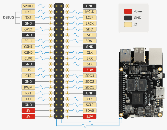
In this article, I used GPIO2_C4(The SDO1 in the picture) as an example to write a simple driver to operate GPIO. The example path in the SDK is
kernel/drivers/gpio/gpio-firefly.c
Next I will describe how to operate GPIO
Input/Output
To begin with, you need to add resource description to the dts (Device Tree) file
kernel/arch/arm64/boot/dts/rk3328-roc-cc.dts:
   firefly-gpio{
          compatible = "firefly,rk3328-gpio";
          firefly-gpio = <&gpio2 GPIO_C4 GPIO_ACTIVE_HIGH>;
          status = "okay";
     };
Here, GPIO2_C4 is defined as the general output input port:
GPIO_ACTIVE_LOW means low level voltage is effective for light on. If high level voltage is effective, replace it with GPIO_ACTIVE_HIGH.
Next, add requesting and controlling of GPIO to the device driver:
static int firefly_gpio_probe(struct platform_device *pdev)
  {
      int ret;
      int gpio;
      enum of_gpio_flags flag;
      struct firefly_gpio_info *gpio_info;
      struct device_node *firefly_gpio_node = pdev->dev.of_node;

      printk("Firefly GPIO Test Program Probe\n");
      gpio_info = devm_kzalloc(&pdev->dev,sizeof(struct firefly_gpio_info *), GFP_KERNEL);
      if (!gpio_info) {
          dev_err(&pdev->dev, "devm_kzalloc failed!\n");
          return -ENOMEM;
       }

      gpio = of_get_named_gpio_flags(firefly_gpio_node, "firefly-gpio", 0, &flag);
      if (!gpio_is_valid(gpio)) {
          dev_err(&pdev->dev, "firefly-gpio: %d is invalid\n", gpio);
          return -ENODEV;
      }
      if (gpio_request(gpio, "firefly-gpio")) {
          dev_err(&pdev->dev, "firefly-gpio: %d request failed!\n", gpio);
          gpio_free(gpio);
          return -ENODEV;
      }
      gpio_info->firefly_gpio = gpio;
      gpio_info->gpio_enable_value = (flag == OF_GPIO_ACTIVE_LOW) ? 0:1;
      gpio_direction_output(gpio_info->firefly_gpio, gpio_info->gpio_enable_value);
      printk("Firefly gpio putout\n");

      gpio = of_get_named_gpio_flags(firefly_gpio_node, "firefly-irq-gpio", 0, &flag);
      printk("firefly:the gpio:%d\n",gpio);
       .......
 }
First call of_get_named_gpio_flags to read number and flag of the gpio named "firefly-gpio" and "firefly-irq-gpio". Use gpio_is_valid to check whether this gpio number is valid, then request this gpio from kernel with gpio_request. If errors occur, call gpio_free to free the gpio which was previously requested successfully. Call gpio_direction_output to set gpio in output direction, with high or low output. Here the flag is GPIO_ACTIVE_LOW, in order to turn on the led, write 0 to it. If you want to read from gpio, you need to set it in input direction before reading the value:
int val;
gpio_direction_input(your_gpio);
val = gpio_get_value(your_gpio);
Here are the definition of some commonly used GPIO APIs:
#include <linux/gpio.h>
 #include <linux/of_gpio.h>
 enum of_gpio_flags {OF_GPIO_ACTIVE_LOW = 0x1,
 };
 int of_get_named_gpio_flags(struct device_node *np, const char *propname, int index, enum of_gpio_flags *flags);
 int gpio_is_valid(int gpio);
 int gpio_request(unsigned gpio, const char *label);
 void gpio_free(unsigned gpio);
 int gpio_direction_input(int gpio);
 int gpio_direction_output(int gpio, int v);
Interruption
The Firefly example program also includes an interrupt pin, and the Interrupts of the GPIO port are analogous to GPIO Input/Output, you need to add resource description to the dts (Device Tree) file first.
kernel/arch/arm64/boot/dts/rk3328-firefly-mini.dts
  gpio {
      compatible = "firefly,rk3328-gpio";
      firefly-irq-gpio = <&gpio2 GPIO_C5 IRQ_TYPE_EDGE_RISING>;  /* GPIO2_C5 */
  };
RQ_TYPE_EDGE_RISING indicates that the interrupt is triggered by a rising edge, the interrupt function can be triggered when a rising edge signal is received on this pin. Here, it may be configured as follows:
IRQ_TYPE_NONE         //Default, no defined interrupt trigger type
IRQ_TYPE_EDGE_RISING  //Rising edge triggers
IRQ_TYPE_EDGE_FALLING //Falling edge trigger
IRQ_TYPE_EDGE_BOTH    //Both rising and falling edges trigger
IRQ_TYPE_LEVEL_HIGH   //High level trigger
IRQ_TYPE_LEVEL_LOW    //Low level trigger
Then the probe function to resolve the DTS, and then apply for interrupt registration, the code is as follows:
static int firefly_gpio_probe(struct platform_device *pdev)
 {
    int ret; int gpio; enum of_gpio_flags flag;
    struct firefly_gpio_info *gpio_info;
    struct device_node *firefly_gpio_node = pdev->dev.of_node;
    ......
    gpio_info->firefly_irq_gpio = gpio;
    gpio_info->firefly_irq_mode = flag;
    gpio_info->firefly_irq = gpio_to_irq(gpio_info->firefly_irq_gpio);
    if (gpio_info->firefly_irq) {
        if (gpio_request(gpio, "firefly-irq-gpio")) {
            printk("gpio %d request failed!\n", gpio);
            gpio_free(gpio); return IRQ_NONE;
        }
        ret = request_irq(gpio_info->firefly_irq, firefly_gpio_irq, flag, "firefly-gpio", gpio_info);
        if (ret != 0)
            free_irq(gpio_info->firefly_irq, gpio_info);
        dev_err(&pdev->dev, "Failed to request IRQ: %d\n", ret);
    }

    return 0;
 }

 static irqreturn_t firefly_gpio_irq(int irq, void *dev_id)
 {
    printk("Enter firefly gpio irq test program!\n");
    return IRQ_HANDLED;
 }
Call gpio_to_irq to convert the PIN value of the GPIO to the corresponding IRQ value, and call gpio_request request to use the IO port, then call request_irq to request an interrupt, if it fails to call free_irq release. gpio_info-firefly_irq request the hardware interrupt number, firefly_gpio_irq is the interrupt function, gpio_info->firefly_irq_mode is the interrupt handling properties, "firefly-gpio" is the device driver name, gpio_info is the device's device structure
Multiplexing
The gpio has multiplexing functions. How to declare it, and how to switch it at the runtime? We take I2C0 for a brief descrition.
Here is what we find in the data sheet:
| Pad# | func0 | func1 |
|---|---|---|
| I2C0_SDA/GPIO2_D1 | gpio2d1 | i2c0_sda |
| I2C0_SCL/GPIO2_D0 | gpio2d0 | i2c0_scl |
We look at the i2c driver kernel/drivers/i2c/busses/i2c-rockchip.c is how to switch multiplexing function:
    static int rockchip_i2c_probe(struct platform_device *pdev){
    struct rockchip_i2c *i2c = NULL; struct resource *res;
    struct device_node *np = pdev->dev.of_node; int ret;
    // ...
    i2c->sda_gpio = of_get_gpio(np, 0);
    if (!gpio_is_valid(i2c->sda_gpio)) {
        dev_err(&pdev->dev, "sda gpio is invalid\n");
        return -EINVAL;
    }
    ret = devm_gpio_request(&pdev->dev, i2c->sda_gpio, dev_name(&i2c->adap.dev));
    if (ret) {
        dev_err(&pdev->dev, "failed to request sda gpio\n");return ret;
    }
    i2c->scl_gpio = of_get_gpio(np, 1);
    if (!gpio_is_valid(i2c->scl_gpio)) {
        dev_err(&pdev->dev, "scl gpio is invalid\n");
        return -EINVAL;
    }

    ret = devm_gpio_request(&pdev->dev, i2c->scl_gpio, dev_name(&i2c->adap.dev));
    if (ret) {
        dev_err(&pdev->dev, "failed to request scl gpio\n");
        return ret;
    }

    i2c->gpio_state = pinctrl_lookup_state(i2c->dev->pins->p, "gpio");
    if (IS_ERR(i2c->gpio_state)) {
        dev_err(&pdev->dev, "no gpio pinctrl state\n");
        return PTR_ERR(i2c->gpio_state);
    }

    pinctrl_select_state(i2c->dev->pins->p, i2c->gpio_state);
    gpio_direction_input(i2c->sda_gpio);
    gpio_direction_input(i2c->scl_gpio);
    pinctrl_select_state(i2c->dev->pins->p, i2c->dev->pins->default_state);
    // ...}
First call of_get_gpio to get the gpio pins from the "gpios" list property in the i2c0 node in device
gpios = <&gpio2 GPIO_D0 GPIO_ACTIVE_LOW>, <&gpio2 GPIO_D1 GPIO_ACTIVE_LOW>;
Then call devm_gpio_request request gpio, followed by calling pinctrl_lookup_state to look up the “gpio” state. The "default" state is already saved in i2c->dev-pins->default_state by the kernel device tree parsing.
Finally, call pinctrl_select_state to select between "default" or "gpio" state, which results in the correspoding multiplexing function.
Here are some commonly used multiplexing APIs:
#include <linux/pinctrl/consumer.h> struct device {//...
    #ifdef CONFIG_PINCTRLstruct dev_pin_info	*pins;
    #endif//...}; struct dev_pin_info {
    struct pinctrl *p;
    struct pinctrl_state *default_state;
    #ifdef CONFIG_PMstruct pinctrl_state *sleep_state;
    struct pinctrl_state *idle_state;#endif };
 struct pinctrl_state * pinctrl_lookup_state(struct pinctrl *p, const char *name);
 int pinctrl_select_state(struct pinctrl *p, struct pinctrl_state *s);
Debugging method
IO
GPIO debugging has a very useful tool, that is, IO instructions, ROC-RK3328-CC Android system default has built-in IO instruction, the use of IO instructions can be read or written in real time the status of each IO port, here a brief IO instructions usage of. First, see the io instructions for help:
#io --help
Unknown option: ?
Raw memory i/o utility - $Revision: 1.5 $

io -v -1|2|4 -r|w [-l <len>] [-f <file>] <addr> [<value>]

   -v         Verbose, asks for confirmation
   -1|2|4     Sets memory access size in bytes (default byte)
   -l <len>   Length in bytes of area to access (defaults to
              one access, or whole file length)
   -r|w       Read from or Write to memory (default read)
   -f <file>  File to write on memory read, or
              to read on memory write
   <addr>     The memory address to access
   <val>      The value to write (implies -w)

Examples:
   io 0x1000                  Reads one byte from 0x1000
   io 0x1000 0x12             Writes 0x12 to location 0x1000
   io -2 -l 8 0x1000          Reads 8 words from 0x1000
   io -r -f dmp -l 100 200    Reads 100 bytes from addr 200 to file
   io -w -f img 0x10000       Writes the whole of file to memory

Note access size (-1|2|4) does not apply to file based accesses.
From the help you can know, if you want to read or write a register, you can use:
io -4 -r 0x1000 //Reads one byte from 0x1000
io -4 -w 0x1000 0x12 //Writes 0x12 to location 0x1000
FAQs
Q1: How do I change the PIN MUX value to a normal GPIO?
A1: When using the GPIO request, the MUX value of the PIN is forced to GPIO, so when using this pin for the GPIO function to ensure that the pin is not used by other modules.
Q2: Why do I read out with the IO command value is always 0x00000000?
A2: If the IO command to read a GPIO register, read out the value is abnormal, 0x00000000 or 0xffffffff, etc., please confirm that the GPIO is not closed CLK. The CLK of the GPIO is controlled by the CRU. You can check whether the CLK is enabled by reading the CRU_CLKGATE_CON * register. If it is not enabled, you can use the io command to set the corresponding register to open the corresponding CLK. After reading the CLK, you can read the correct Of the register value.
Q3: What should I do when I measure the voltage of the PIN pin incorrectly?
A3: If the voltage of this pin is not measured correctly, if the external factor is excluded, you can check whether the voltage source of the pin is correct and the IO-Domain configuration is correct.
Q4: What is the difference between gpio_set_value() and gpio_direction_output()?
A4: If you use the GPIO, do not dynamically switch the input and output, it is recommended to set the GPIO output direction at the beginning, followed by pulling down the use of gpio_set_value() interface, rather than the proposed gpio_direction_output(), because gpio_direction_output interface Mutex locks, there is an error exception to the interrupt context call, and gpio_direction_output does more and more waste than gpio_set_value.


