UART
Update time:2018-04-13 Views:3360
Introduction
Firefly-RK3399 development board supports 5 independent UART controller:UART0,UART1,UART2,UART3,and UART4,each with two 64-byte FIFO buffers for data reception and transmission. among them:
UART0 for Bluetooth transmission, UART2 for debugging serial port, only UART0 and UART3 support hardware automatic flow control.
Support bit rate 115.2Kbps, 460.8Kbps, 921.6Kbps, 1.5Mbps, 3Mbps, 4Mbps.
Supports programmable baud rates even,even with non-integer clock divider.
Supports interrupt-based or DMA-based modes
Support 5-8 bit width transfer
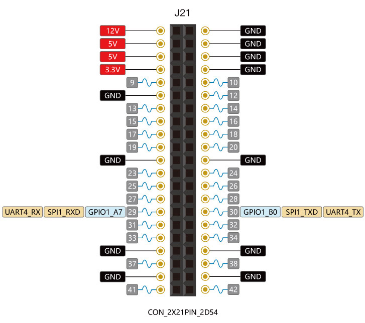
Our Firefly-RK3399 development board for the convenience of users, leads to a row of general-purpose GPIO, the corresponding schematic is as follows:
GPIO1_A7 and GPIO1_B0 can be reused as uart4_rx and uart4_tx,
DTS Config
The file kernel/arch/arm64/boot/dts/rockchip/rk3399.dtsi has the definition of UART nodes:
   aliases {
       ...
       serial0 = &uart0;
       serial1 = &uart1;
       serial2 = &uart2;
       serial3 = &uart3;
       serial4 = &uart4;
   };
serial0 is defined in "aliases" node as: serial3 = &uart0;
Because our Firefly-RK3399 development board opens the uart4 for the user to use, using uart4 as an example to introduce the use of the serial port. The following are the uart4 node-related definitions:
   uart4: serial@ff370000 {
       compatible = "rockchip,rk3399-uart", "snps,dw-apb-uart";
       reg = <0x0 0xff370000 0x0 0x100>;
       clocks = <&pmucru SCLK_UART4_PMU>, <&pmucru PCLK_UART4_PMU>;
       clock-names = "baudclk", "apb_pclk";
       interrupts = <GIC_SPI 102 IRQ_TYPE_LEVEL_HIGH 0>;
       reg-shift = <2>;
       reg-io-width = <4>;
       pinctrl-names = "default";
       pinctrl-0 = <&uart4_xfer>;
       status = "disabled";
   };
   uart4 {
       uart4_xfer: uart4-xfer {
       rockchip,pins =
               <1 7 RK_FUNC_1 &pcfg_pull_up>,
               <1 8 RK_FUNC_1 &pcfg_pull_none>;
       };
   };
You only need to enable the node in the kernel/arch/arm64/boot/dts/rockchip/rk3399-firefly-port.dtsi file,as follows:
&uart4 {
       current-speed = <9600>;
       no-loopback-test;
       status = "okay";
};
UART̩̠_RX and UART̩_TX can be reused as SPI1_RXD and SPI1_TXD, so be careful to shut down the use of spi1,as follows:
&spidev0 {
	status = "disabled";
};
Debugging method
You can now communicate with the uart4 via a USB-to-serial adapter in your host PC. Follow the steps below:
(1) Connect the uart port.
Connect the TX, RX, GND pins of uart4 to the serial adapter's TX, RX, GND pins respectively.
(2) Open a serial terminal in host PC.
Run kermit in a shell window, and set baud rate:
$ sudo kermit
C-Kermit> set line /dev/ttyUSB0
C-Kermit> set speed 9600
C-Kermit> set flow-control none
C-Kermit> connect
* /dev/ttyUSB0 is the device file of USB-to-serial adapter.
* baud is the "current-speed" attribute in the DTS node.
(3) Transmit data.
The device file for uart4 is /dev/ttyS4. Run the following command in device:
echo firefly uart4 test... > /dev/ttyS4
The serial terminal in the host PC will receive string "firefly uart4 test...".
(4) Receive data.
First, run the following command in device:
cat /dev/ttyS4
Then input string "Firefly uart4 test..." in the serial terminal.You can see the same string received in the device.
FAQs
Q1: Why is the system error after connecting to the serial adapter?
A1:Firefly RK3399 development board's TX and RX, respectively, corresponding to the serial port adapter's TX and RX, If confused, it will lead to serial communication error.


